Marlin Unified Bed Leveling (UBL) with Probe Manually
This post is an update on Marlin Manual Mesh Leveling). Shortly after writing that, I decided to take the plunge and move to using Marlin's Unified Bed Leveling (UBL) system over MBL. And I'm glad I did! I'd recommend it for anyone using MBL or even ABL, with or without a probe.
Without a probe, the overall process will be similar to MBL, but the Marlin commands are different and UBL offers some more functionality as well.
Unified Bed Leveling
Similar to ABL and MBL, UBL must be enabled in Marlin.
In Configuration.h:
First enable UBL
//#define AUTO_BED_LEVELING_3POINT
//#define AUTO_BED_LEVELING_LINEAR
//#define AUTO_BED_LEVELING_BILINEAR
#define AUTO_BED_LEVELING_UBL
//#define MESH_BED_LEVELING
In older versions of Marlin, UBL would automatically enable using the mesh after G28. But, that behavior was opposite of the other bed leveling options and may have been confusing. These days you get a warning if you don't explicitly enable or disable the behavior.
Since I've already got the proper start-gcode for enabling it, I'll just disable this behavior so it works like ABL and MBL do:
/**
 * Normally G28 leaves leveling disabled on completion. Enable
 * this option to have G28 restore the prior leveling state.
 */
//#define RESTORE_LEVELING_AFTER_G28

// UBL used to enable the above by default
#define RESTORE_LEVELING_AFTER_G28 false
Next the options for UBL:
- MAX_POINTS_X will control how dense the mesh is. 3 is a good starting point, 5 or 7 is probably about the most you'd want to do when probing manually.
#elif ENABLED(AUTO_BED_LEVELING_UBL)

  //===========================================================================
  //========================= Unified Bed Leveling ============================
  //===========================================================================

  //#define MESH_INSET 0             // Set Mesh bounds as an inset region of the bed
  #define GRID_MAX_POINTS_X 5       // Don't use more than 15 points per axis, implementation limited.
  #define GRID_MAX_POINTS_Y GRID_MAX_POINTS_X

  #define UBL_SAVE_ACTIVE_ON_M500   // Save the currently active mesh in the current slot on M500
Manual Probing
The comments in Configuration.h don't really make it clear that UBL can be used without a probe or how to do so. But it's a simple define in Configuration.h at the top of the probe section:
#define PROBE_MANUALLY
That's it!
Initial Leveling
Assuming you have everything above enabled, built Marlin and flashed it, you can start using UBL.
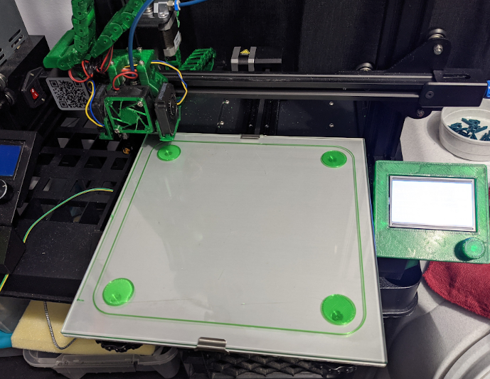
But First! ...level the bed. My method of using UBL with manually probing has the corners set to 0.0. With this approach, UBL isn't used to 'level' the bed, but to account for the tiny variations in the height of it.
So level the bed so that a test pattern printed over each knob print correctly:
Initial Mesh Calibration
The mesh can be generated one of two ways:
- automated manual probing
- manual editing
Automated Manual Probing
If your bed has large variations, so much that printing a test pattern isn't possible, or you just have no idea what the general shape of the bed is, starting with the automated probing is probably a good idea. This can be reached via an LCD menu, or by sending the G29 P2 command to the printer. In either case, the printer will guide you through probing each point (either on the LCD or through the serial output).
Manual Editing
You don't have to do the above, though, especially if you can print a test pattern without risk of damaging the nozzle. In that case, create a new 'zero' mesh by sending a G29 P0 command.
Save the Mesh
Unlike ABL and MBL, UBL saves meshes independently from the rest of the settings saved in EEPROM. And, you can save multiple meshes that can be loaded later. This is useful if you have multiple glass beds that can be interchanged, for example.
To save the current mesh, send the G29 SN command where N in SN is a 'slot' number beginning at 0, ie G29 S1. The number of slots will depend on your printer's hardware and the size of the configured mesh, but the maximum number should be reported in the output of M503.
Configure Start-GCode
Above I mentioned the configuration definition for not enabling leveling after homing. This is the default behavior for past leveling systems in Marlin and I wanted to be consistent. But, this means that start gcode should be modified in the slicer.
It's simple, just add M420 S1 after G28:
M190 S[first_layer_bed_temperature]
M104 S[first_layer_temperature]

; Beep
M300 S400 P250

G28 ; home all axes
M420 S1 ; use bed level mesh

...
Editing the Mesh
At this point, you have a mesh saved. Even if you used G29 P2 or the LCD menu to interactively probe the mesh, it's likely that you'll still need to adjust it.
To adjust the mesh, first print a test pattern similar to the 4 corners above, but with a pattern over each mesh point:
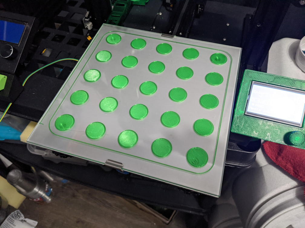
Then, look at the test pattern at point. If the test pattern indicates the nozzle was too close to the bed (infill is rough, had ridges or is even going transparent), edit that mesh point to be higher. If the nozzle was too far away (infill not touching or even not adhering at all), edit the point to be lower.
To edit the points:
First, take a look at the entire mesh by running M420 V1:
Send: M420 V1
Recv:
Recv: Bed Topography Report:
Recv:
Recv:     ( 30,200)                      (200,200)
Recv:         0       1       2       3       4
Recv:  4 |  0.000   0.000   0.000   0.000   0.000
Recv:    |
Recv:  3 | +0.050   0.000  +0.050  -0.025  -0.025
Recv:    |
Recv:  2 | +0.100  +0.150  +0.175  +0.075   0.000
Recv:    |
Recv:  1 |  0.000   0.000  +0.075  +0.150  +0.200
Recv:    |
Recv:  0 |[ 0.000]  0.000   0.000   0.000   0.000
Recv:         0       1       2       3       4
Recv:     ( 30, 30)                      (200, 30)
Recv:
Recv: Mesh is valid
Recv: Storage slot: 0
Recv: echo:Bed Leveling OFF
Recv: echo:Fade Height OFF
Recv: ok
Next, decide what point you want to adjust and determine the row and column numbers. Set the new value of the point by running M421 Jc Ir Zb where c is the column number, r is the row number and b is the new z value. For example, M421 J1 I2 Z0.1 would adjust the value of the point in row 2 (the middle row) and column 1 (the second column), shown above with a value of 0.150 to the value of 0.100.
If you are adjusting the mesh in response to a test print, move the value up or down in 0.05mm increments.
Repeat this to adjust all points as necessary. Then save the mesh as before, i.e. G29 S1.
Finally, print another test pattern with the updated mesh and verify the changes made above were correct. When generating a new mesh, multiple iterations may be required to get the perfect mesh dialed in.
Interactive Mesh Editing in OctoPrint
I have written an OctoPrint plugin that will run all of these commands for you and allow the mesh to be edited interactively. It can be found here: https://github.com/The-EG/OctoPrint-UBLMeshEdit
Mesh Test Pattern
The mesh test pattern I use above is a customizable OpenSCAD script. It can be found here: https://www.thingiverse.com/thing:4764660