Knurled Knobs in FreeCAD
Knurly, Dude!
The 3D Printing adventures continue, and as I find myself designing things I had the question: how can I make knurled surfaces in FreeCAD?
After some research and combining a few different techniques, here’s what I came up with.
Creating Knurling
This technique only works on circular surfaces (cylinders), but that’s ok because most knobs and handles are round anyway…
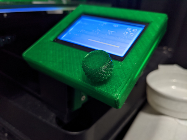
For this example, I made a knob for my 3D Printer’s LCD encoder in FreeCAD version 0.19. Actions specified are in the ‘Task’ pane.
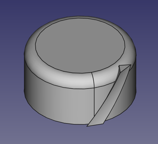
First, create a simple knob:
- Select Part Design Workbench
- Create Body
- Create Sketch (select XY_Plane)
- Add a cirlce with a radius of 10 mm, snapped to the center origin
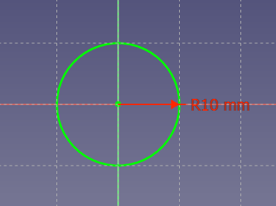
- Close the sketch
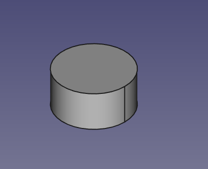
- Pad it by 10 mm
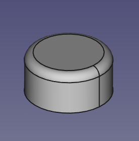
- Select the top edge
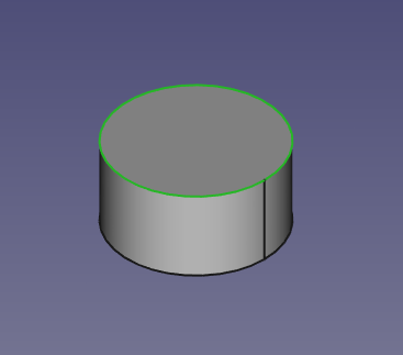
- Fillet 2 mm
- Select the bottom face
- Create Sketch
- Add a circle with a radius of 7 mm, anchored to the origin
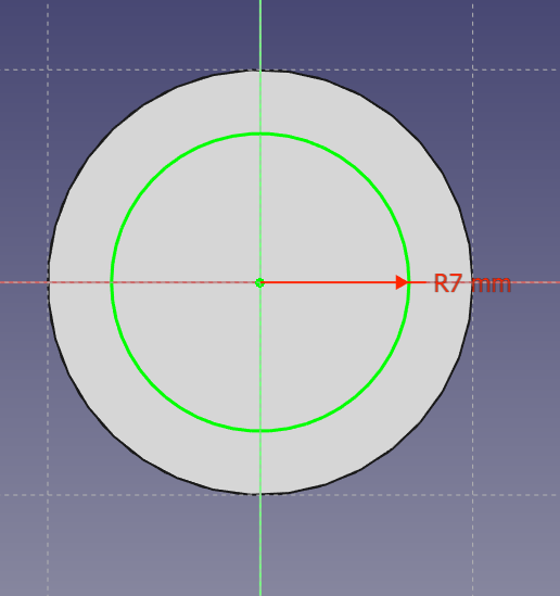
- Pocket 9 mm
- Select the new inner face
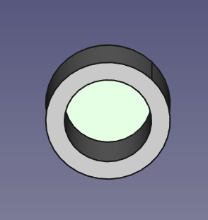
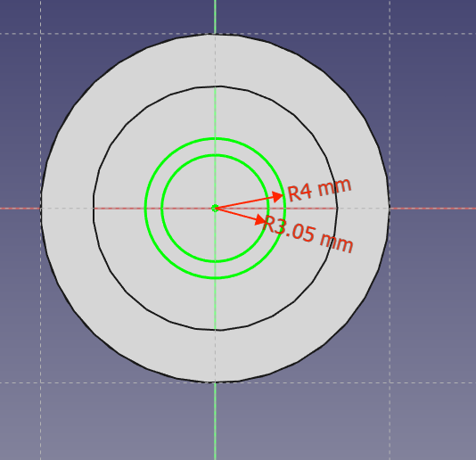
- Create Sketch
- Create two circles, both centered on the origin
- One with a radius of 4 mm
- One with a radius of 3.05 (6.1 / 2 - the LCD encoder shaft is 6mm in diameter)
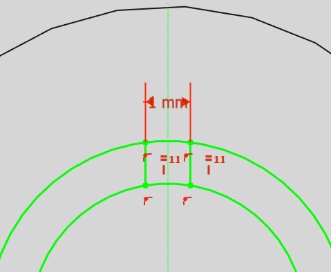
- Add 2 vertical lines near the top of the circles, connecting them
- Attach the endpoints of each line to both circles (Fix Point onto an Object constraint)
- Give both lines a vertical constraint
- Give both lines equali1ty constraint (select both and select the ‘=’ constraint)
- Constrain the lines to be 1 mm apart horizontally
- Select the top vertex of each line
- Shift-H
- Specify 1 mm
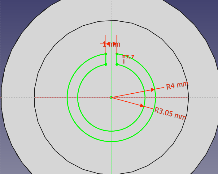
- Use the Trim Edge tool to remove the portion of the circles between the lines:

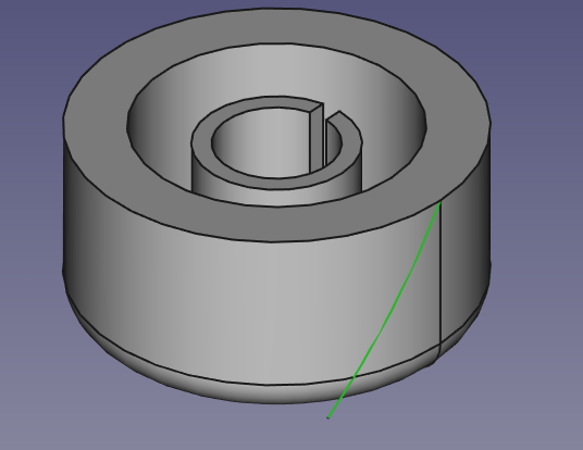
- Pad by 8 mm
So that’s a simple knob. Now on to the knurling:
- Select Part Workbench
- Part->Create Primitives
- Select Helix
- Radius is the same as the knob (10 mm)
- Height is the same as the knob (10 mm)
- Pitch 10 x height (100 mm)
- Click Create
- Click Close
- Select Part Design Workbench
- Select the helix
- Part Design->Create Body
- Create Sketch
- Select XY_Plane001
- Hide the knob for now (Select ‘Body’ in the Model pane and press space)
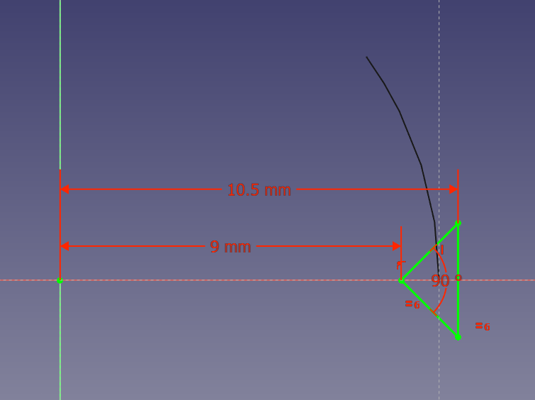
- Draw a triangle near the base of the helix:
- One point constrained to the x axis
- The angle at that point constrained to 90 degrees
- Constrain the two connecting segments to be equal length
- Constrain that point to be 9 mm from the y axis
- Constrain one of the other points to be 10.5 mm from the y axis
- Constrain the far edge to be vertical
- Close sketch
- Additive Pipe
- Under ‘Path to sweep along’ click Object
- Select the helix
- Select ‘Frenet’ for Orientation Mode
- Make the knob visible again (Select ‘Body’ in the Model pane and press space)
- Select Draft Workbench
- Select the helix pipe (Body001) in the Model Pane
- Modification->Array Tools->Polar Array
- Number of elements = 20
- Click Reset point and verifty X, Y, Z = 0
- Click OK
- Copy the array
- Select the array (Array) in the Model pane and press Ctrl-C
- Leave all objects selected and click OK
- Press Ctrl-V
- Change the new helix to left-handed
- Select the copied helix (Helix001)
- In the properties panel below, change local coord to ‘Left Handed’
- Cut the helixes from the knob
- Select Part Workbench
- Select the knob (Body)
- Hold Ctrl and select Array
- Part->Boolean->Cut
- Select Cut
- Hold Ctrl and Select Array001
- Part->Boolean->Cut
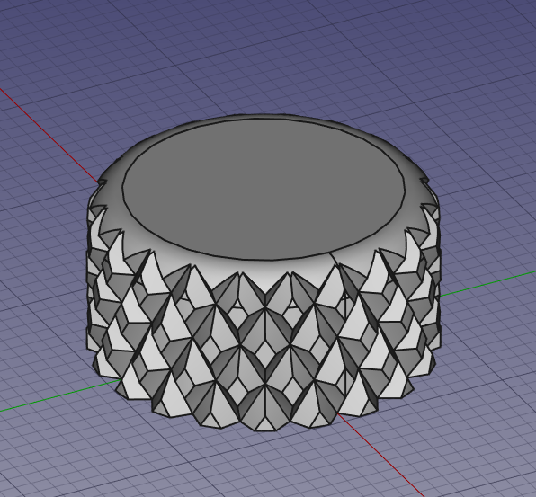
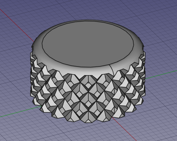
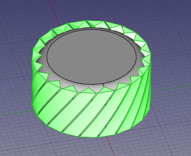
There! A knurled knob. I didn’t quite like it yet, though. But, tweaking it is easy since FreeCAD is parametric.
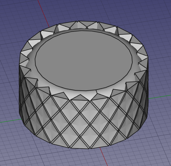
I ended up tweaking the helixes a bit:
- Select Helix in the Model Pane
- Change Pitch to 75 mm
- Change Height to 9.25 mm
- Select Helix001 and repeat 2 & 3
That’s better, I think: