Marlin Manual Mesh Bed Leveling
The print beds on 3D printers aren’t always perfectly flat. Sometimes you can get lucky and get a pefectly flat surface to print on, but considering the materials the bed is made out of and the constant heat cycling, it’s more likely that you’ll have to deal with at least some warping.
Mesh Bed Leveling
There are few options for compensating for a warped bed, but I chose to use Mesh Bed Leveling because it didn’t require any extra hardware or tools.
This does require building a custom configuration for Marlin.
At a minimum, enable mesh bed leveling in Configuration.h:
#define MESH_BED_LEVELINGSome of the mesh leveling configuration may need to be tweaked as well:
#elif ENABLED(MESH_BED_LEVELING)

  //===========================================================================
  //=================================== Mesh ==================================
  //===========================================================================

  #define MESH_INSET 30          // Set Mesh bounds as an inset region of the bed
  #define GRID_MAX_POINTS_X 3    // Don't use more than 7 points per axis, implementation limited.
  #define GRID_MAX_POINTS_Y GRID_MAX_POINTS_X

  //#define MESH_G28_REST_ORIGIN // After homing all axes ('G28' or 'G28 XYZ') rest Z at Z_MIN_POS

#endif // BED_LEVELING
#define MESH_INSET 30 sets how far from the edge of the bed the first and last mesh points are. I like having the corners of the mesh directly over the bed screws so I use a value of 30.
#define GRID_MAX_POINTS_X 3 defines how many points are used in the mesh (GRID_MAX_POINTS_Y is defined as the same value, so the mesh is square). 3 is the default value and results in a 9 point, 3x3, mesh. This is good to start out with, but you may want to use a 5x5 mesh later.
It’s also possible to include LCD menus for setting up the mesh data and interactively editing it:
#define LCD_BED_LEVELING

#if ENABLED(LCD_BED_LEVELING)
  #define MESH_EDIT_Z_STEP  0.025 // (mm) Step size while manually probing Z axis.
  #define LCD_PROBE_Z_RANGE 4     // (mm) Z Range centered on Z_MIN_POS for LCD Z adjustment
  #define MESH_EDIT_MENU        // Add a menu to edit mesh points
#endif
And, a menu item that allows for easy leveling of the four corners:
#define LEVEL_BED_CORNERS

#if ENABLED(LEVEL_BED_CORNERS)
  #define LEVEL_CORNERS_INSET_LFRB { 30, 30, 30, 30 } // (mm) Left, Front, Right, Back insets
  #define LEVEL_CORNERS_HEIGHT      0.0   // (mm) Z height of nozzle at leveling points
  #define LEVEL_CORNERS_Z_HOP       4.0   // (mm) Z height of nozzle between leveling points
  //#define LEVEL_CENTER_TOO              // Move to the center after the last corner
#endif
Initial Leveling
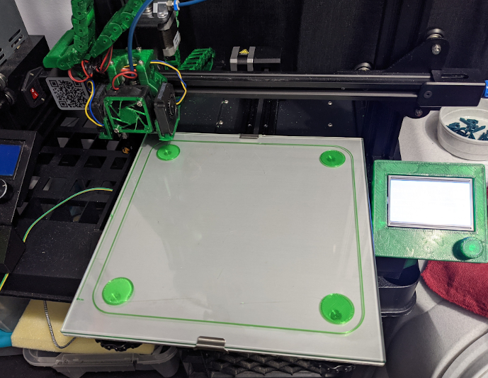
Before trying to account for any warping, the bed needs to be leveled properly at the corners.
I print a test pattern in just the corners above the screws. It may take a few prints to get everyting adjusted to the point where all four corners are printing properly:
Manual Mesh Calibration
Once the corners are leveled properly, the mesh can be calibrated using a similar test pattern, but with a circle at each mesh point.
If you have a already good idea of the shape of the bed you can edit the mesh first, but if not, print the test pattern out:
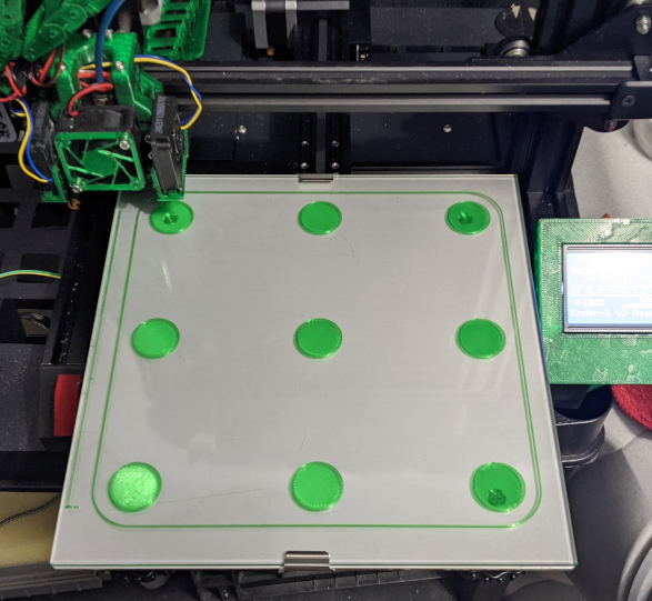
Note: each time you print the test pattern out, the 4 corners should always be good. If they aren’t, the bed has moved and you need to level the corners again!
Mesh Editing
With the test pattern printed, the mesh needs to be edited for any point that isn’t printing properly.
First, take a look at the existing mesh. In OctoPrint or PronterFace send G29 S0 to the printer.
If nothing has been changed yet you won’t have a mesh:
Send: G29 S0
Recv: Mesh Bed Leveling has no data.
Recv: X:0.00 Y:116.66 Z:10.19 E:0.00 Count X:0 Y:9333 Z:4076
Recv: ok
Otherwise the existing mesh will be shown:
Send: G29 S0
Recv: Mesh Bed Leveling OFF
Recv: 3x3 mesh. Z offset: 0.00000
Recv: Measured points:
Recv:         0        1        2
Recv:  0 +0.00000 -0.15000 -0.00000
Recv:  1 +0.05000 -0.15000 -0.05000
Recv:  2 -0.00000 -0.05000 -0.00000
Recv:
Recv: X:0.00 Y:116.66 Z:10.19 E:0.00 Count X:0 Y:9333 Z:4076
Recv: ok
For each point in the mesh, other than the corners, adjust the value based on if the nozzle should be lower (less than 0) or higher (more than 0). It is best to make adjustments in 0.05mm increments at first.
To set a point use G29 again, but with the S3 option specifying the grid column with I, row with J and z adjustment with Z. The column and row numbers start from 0 and are shown in the output of G29 S0 along the top and left of the mesh grid. For a 3x3 mesh, I1 J1 is the center point.
For example, to set the middle point to be 0.1mm higher than the corners, the command would be G29 S3 I1 J1 Z0.1:
Send: G29 S3 I1 J1 Z0.1
Recv: X:0.00 Y:117.58 Z:20.15 E:0.00 Count X:0 Y:9406 Z:8059
Recv: ok
Verify the change (G29 S0):
Send: G29 S0
Recv: Mesh Bed Leveling OFF
Recv: 3x3 mesh. Z offset: 0.00000
Recv: Measured points:
Recv:         0        1        2
Recv:  0 +0.00000 +0.00000 +0.00000
Recv:  1 +0.00000 +0.10000 +0.00000
Recv:  2 +0.00000 +0.00000 +0.00000
Recv:
Recv: X:0.00 Y:116.66 Z:10.19 E:0.00 Count X:0 Y:9333 Z:4076
Recv: ok
Repeat for any other points that need adjustment. Then save the mesh to the EEPROM with M500:
Send: M500
Recv: echo:Settings Stored (734 bytes; crc 59364)
Recv: ok
Using a Stored Mesh
By default, the printer won’t use a stored mesh after auto homing. A command must be added to the slicer’s Start G-Code to enable the mesh, after the G28 command:
M420 SHowever, that command will fail if the mesh has not been setup yet. So, only add the command after editing the mesh for the first time.
Iterate
Now that a mesh is defined, add the M420 S command to your slicer’s starg g-code, reslice the test pattern and print it again. Make any additional adjustments. It may take a few times to get all of the points adjusted properly.
At this point, the mesh should be setup and good. It shouldn’t need to be adjusted unless the bed is changed.