Using a 3D Printer '12864' LCD Screen on a Raspberry Pi
Small LCD screens are convenient way to display some information without requiring a full blown X server or similar setup. And most importantly, I had a spare LCD screen from one of my 3d printers sitting, unused, on a shelf; so it was ‘free’ in this case.
The CR10_STOCKDISPLAY ie. a ‘12864’ LCD
The LCD in question is a common ‘12864’ LCD, ie. 128x64 pixels, CR10_STOCKDISPLAY as it’s known in Marlin. This is actually an ST7920, and there is a fair amount of documentation available for it.
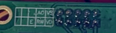
The only problem is that this LCD screen was intended to be connected to a 3d printer controller board, and so the normal pinout and connection documentation was not helpful. Luckily there is some info out there to help. First, the connectors on the LCD do have some labels:
And the pins definition for the older Creality 1.x boards in Marlin also has some helpful info:
               EXP1 as CR10 STOCKDISPLAY
                         ------
             BEEPER_PIN | 1  2 | BTN_ENC
                BTN_EN1 | 3  4 | RESET
                BTN_EN2   5  6 | LCD_PINS_D4     (ST9720 CLK)
(ST9720 CS) LCD_PINS_RS | 7  8 | LCD_PINS_ENABLE (ST9720 DAT)
                    GND | 9 10 | 5V
                         ------
So, from that we can match up the pins on the connector to the pins listed in the ST7920 documentation:
    VD = 5v/vcc
    VS = gnd
    AO = CS
    RW = DAT
     E = CLK
Raspberry Pi SPI
Enabling SPI on the Raspberry Pi is simple, just use raspi-config. With the above info on the pins, it should be simple just just connect up vcc to 5v, gnd to gnd, DAT to SPI0 MISO, CLK to SPI0 SCLK and finally AO to SPI0 CE0.
The screen does power on, but it doeesn’t work.
Burried in the Raspberry Pi Documentation is this tidbit:
Setup and hold times related to the automatic assertion and de-assertion of the CS lines when operating in DMA mode are as follows:
So, it appears that the CS pins are only toggled during DMA mode, which is only triggered on ‘larger’ transfers. It might be possible to manually manage the CS pin, but in this case the interface to the LCD is write only, so just holding it high continously is enough.
Instead of connecting AO to SPI0 CE0, loop AO back to VD on the other connector on the LCD, or just connect it to another 5v. Success!
Well, sort of.
I was using a python module I found to test if the screen worked before bothering to write my own code for it. It was sort of working, text would display, etc. but there were artifacts too.
I thought perhaps some of this was due to python and odd timing/delays, so I started developing something in C++. My code produced even worse results! Using the delays mentioned in the ST7920’s documentation, usually on the order of 75 microseconds or so, ended up with odd characters on the screen and other things. Even using delays up to multiple miliseconds did not work well.
SPI Clock Speed
Finally I decided to dig into how the python module above was working since it appeared to be doing a bit better than my code and I also researched a few other ST7920 specific examples around the web. Pretty much every code I could find setup the SPI to use a speed of 1.8MHz.
On a whim, I decided to decrease this to 400KHz, and success! I could reduce the delays down to 75 microseconds and everything worked properly. Some trial and error showed that a speed up to 1.5MHz seemed to work well, still with the small delays the documentation called for.
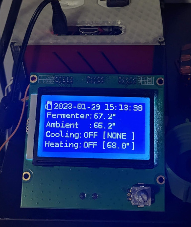
At this point I was able to update the entire display mutliple times per second with no flickering or artifacts. It actually works better than with Marlin!
Coding an Interface
With the SPI Working properly, coding the interface is actually pretty simple. Everything is documented in the ST7920 documentation.
My C++ interface can be found in my brewserver repo: st7920.cpp/st7920.h. This includes rendering freetype fonts instead of the LCDs built in font.